Prototype Development - Hardware
This post is specifically going to address what sensors we used, why we used them and how they work together.
Photo Interrupter
One of the sensors that we are using is called a Photo Interrupter. A Photo Interrupter detects when something is blocking a light source directed at it. We decided to use this sensor in order to check for the shelf facing. So the way it works is if there is an object between the sensor, it detects it and sends data. If there is no object detected, it would mean that the shelf is empty and it needs to be restocked. Initially, we were debating between using either a Photo interrupter or a Magnetometer, but we decided that a Photo Interrupter served better for the purpose of our project.
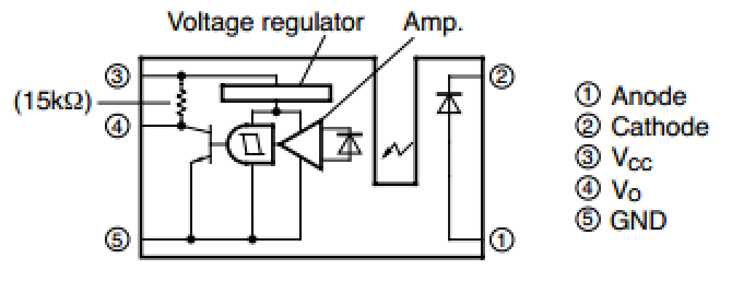
As mentioned in this article, this sensor has 5 pins and the following diagram can be used to connect this sensor to the breadboard.

For this sensor, there are three pins on one side and two pins on the other side. For the side that has 2 pins, the shorter pin in the anode and the longer pin is the cathode. The side that has 3 pins, the small one corresponds to Vo, the long one corresponds to Vcc, and the medium one corresponds to the ground.
Note: Understanding the diagram above is very important because there is a high chance of frying the sensor.
PIR Motion Sensor
The second sensor that we are using is called a PIR Motion Sensor. This sensor is used to track customer movement throughout the store. When someone is standing in front of the sensor, it detects that person and sends the data.
This sensor has three different connections: The connections being DC 12V, Alarm and Ground.
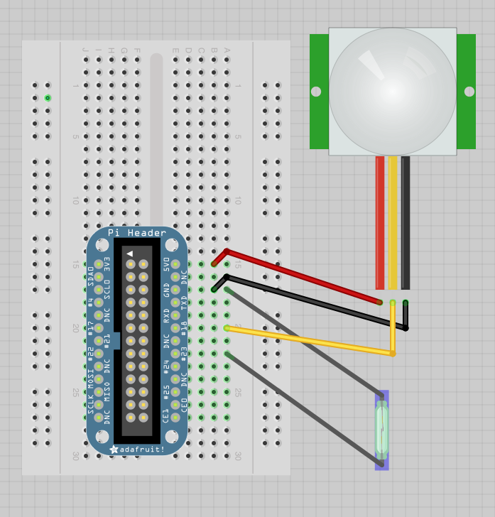
The diagram below was followed in order to connect this sensor to the Raspberry Pi. The red wire goes to 5V, the yellow wire goes to GPIO pin#18, and the black wire goes to ground.

Note: Understanding the above diagram is very important.
Equipment
We currently have three Raspberry Pi’s setup for collecting and sending data. Each Raspberry Pi has two sensors connected to it. The equipment that is currently being used are 3 Raspberry pi’s, 3 Photo Interrupters, 3 PIR Motion Sensors, 3 LED’s, 3 Breakout cables and a few wires. The functionality of the LED on the breadboard is that if there is a motion detected or if there is an object in between the sensor, the LED light goes off.
The diagram below shows how the sensors are connected to the raspberry pi. Hopefully this helps!

