Improving Prototype Usability
As much as we enjoyed playing with sensors, the LASS prototype wasn’t supposed to be used only by the developers. This post considers the steps we took to make our prototype as hands free as possible, so that the user - potentially a store manager - can just plug it in and go.
Plug In and Go
During the development process, we found the most efficient way to get things done was to write code directly onto the RaspberryPi itself. This allowed us to test the sensor functions and GPIO libraries as we went along, but also required us to view the display via HDMI cable.
Now that the sensors have been tested and are fully operational, there is no longer a need to view the screen or interact with the interface at all, on the conditions that we:
- Can run the code automatically
- Are given some sort of confirmation that the system is running error free.
Run On Start Up
To run the sensor scripts automatically without help of any screen, mouse, or keyboard, we set the scripts to run on start up. This was completed via the following steps in terminal:
Create a folder in which to store the auto running script
$ mkdir ~/bin
$ cd ~/bin
Create and edit the script as root:
# nano script_auto_run
The script should read:
#!/bin/bash
# Script to start our application
echo "Doing autorun script..."
sudo /path/to/script &  (If you wanted to add a python file, the last line would read "sudo python /path/...")
Make the script executable (again, as root)
# chmod +x script_auto_run
Lastly, make the following edits as root to /etc/rc.local
# nano /etc/rc.local
add the following line to the end of the file:
/home/pi/bin/script_auto_run
Saving the path of script_auto_run in this file will run the application on start up.
LEDs for Posting Observations
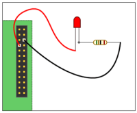
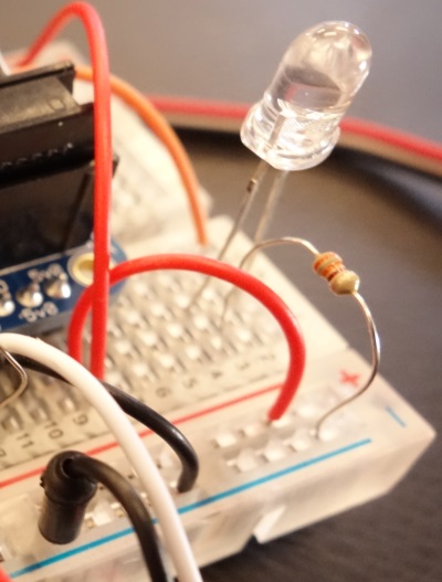
The second condition as listed above was satisfied by setting an LED to blink once an observation was confirmed to be posted. We managed this by connecting an LED to a GPIO pin on the RaspberryPi, with wiring similar to the diagram below. The resistor used was 330 ohms. It is important to use the 330Ohm resistor only because otherwise it would be giving you many errors.

The GPIO pin used was pin #4 in terms BCM references, and it was set up in much the same way as the GPIO pins #17 and #18, except it was set to output rather than input.
After that, all we had to do was tell it when to light up using the following line:
GPIO.output(GPIO_LED,True)
The blinking of the LED is positioned effectively in the script to ensure that the prototype is not only collecting data, but also posting it to the SensorThings API data service as well.

